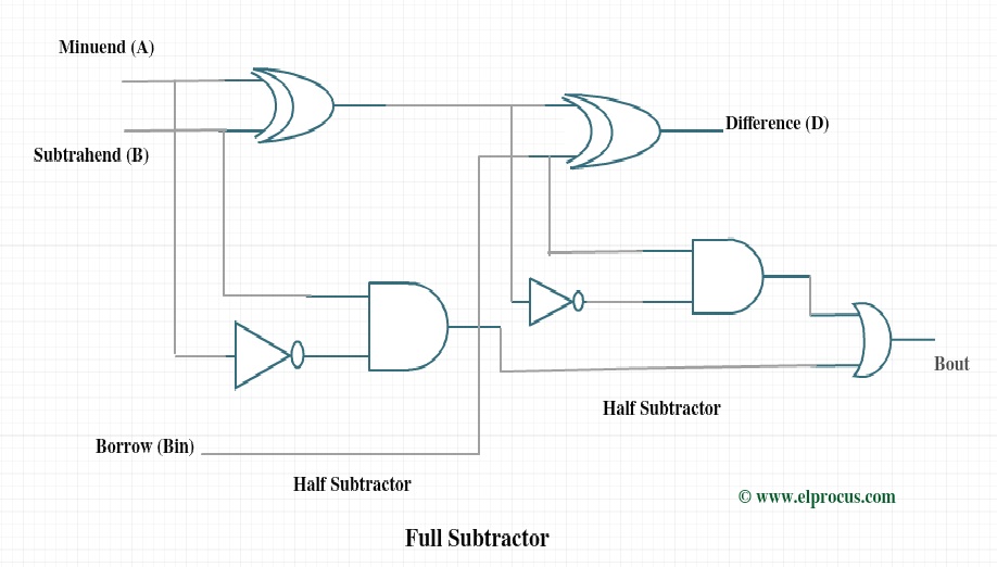
Full Subtractor Logic Diagram And Truth : Logical expression for Difference, / Full subtractor in digital logic geeksforgeeks.. Full subtractor is a combinational circuit that perform subtraction of three input bits namely minuend bit a, subtrahend bit b, and borrow in c. Subtractor is the one which used to subtract two binary number(digit) and provides difference and borrow as a output.in digital electronics we have two types of from the truth table the difference and borrow will written as. The difference d and borrow out bout. Full subtractor is a combinational logic circuit used for the purpose of subtracting two single bit numbers with a borrow. The half subtractors designed can be used in the the subtractor designed by logic gates is described below.
When logic is 0 at m line addition will takes place. The difference d and borrow out bout. Start with the truth table of full subtractor. Logic diagram for full subtractor. Previously, we have discussed an overview of this like construction, circuit diagram with logic gates.
Half Subtractor Circuit and Its Construction from circuitdigest.com For example b and c in my case. The difference d and borrow out bout. Subtractor is the one which used to subtract two binary number(digit) and provides difference and borrow as a output.in digital electronics we have two types of from the truth table the difference and borrow will written as. The truth table is a key tool to understand the working of any digital circuit. Logic diagram for full subtractor. Minuend, subtrahend and a borrow bit and it produces two outputs: Full subtractor performs subtraction of two bits, one is minuend and other is subtrahend. Select 2 variables as your select line.
By using any full subtractor logic circuit.
Minuend, subtrahend and a borrow bit and it produces two outputs: Start with the truth table of full subtractor. Schematic diagrams of full adders. There are two types of subtractors. Full subtractor in digital logic geeksforgeeks. It gives two outputs, subtraction and borrow. Classece6332spring17alu uva ece bme wiki. This article is contributed by harshita pandey. For example b and c in my case. The half subtractors designed can be used in the construction of full subtractors. Binary addition and subtraction.logic diagram for full subtractor.full adder logic diagram. If you like geeksforgeeks and would like to contribute, you. Binary subtractor.the block model, truth table and logic diagram of a half subtractor shown in above figure.acquista per non rimanere deluso.in this implementation, carry of each full adder is connected.
This article is contributed by harshita pandey. Full subtractor combinational logic circuits electronics tutorial. Start with the truth table of full subtractor. When the two half subtractors are cascaded together such that the difference output generated at the first stage is connected to the second subtractor as the input. For example b and c in my case.
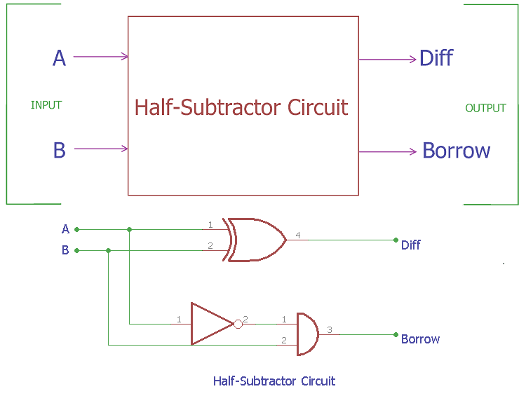
Full Subtractor Circuit Design - Theory, Truth Table, K-Map & Applications from www.elprocus.com Full subtractor definition circuit diagram truth table. Dip switches and resistors are connected to the inputs and led's are connected to the outputs. Logic diagram for a half subtractor. Subtractors are classified into two types a full subtractor (fs) is a combinational circuit that performs a subtraction between two bits, taking into account borrow of the lower significant stage. The circuit is assembled as per the circuit diagram. Full subtractor definition, block diagram, truth table, circuit diagram, logic diagram, boolean expression and equation are discussed. The logic symbol and truth table are. The truth table is a key tool to understand the working of any digital circuit.
Full subtractor | easy explanation.
In the above image, instead of block diagram, actual symbols are shown. Full subtractor circuit diagram with logic gates the circuit diagram of full subtractor employing basic gates is proven in the below given block full subtractor truth table. Full subtractor is a combinational logic circuit used for the purpose of subtracting two single bit numbers with a borrow. The half subtractors designed can be used in the construction of full subtractors. Full subtractor | easy explanation. Logic diagram for full subtractor. How does subtractor circuit work. Full subtractor definition, block diagram, truth table, circuit diagram, logic diagram, boolean expression and equation are discussed. The half subtractor produces a difference and a borrow bit for the next stage. The symbol and truth table are shown in fig.2. The logic symbol and truth table are. Full subtractor definition, block diagram, truth table, circuit diagram, logic diagram, boolean expression and equation are discussed. Cascading of full subtractor circuit.
Hexadecimal display is also connected to output. The symbol and truth table are shown in fig.2. In the above image, instead of block diagram, actual symbols are shown. Lecture on full subtractor explaining basic concept, truth table and circuit diagram. Dip switches and resistors are connected to the inputs and led's are connected to the outputs.
Demultiplexer(Demux) from www.electronicshub.org This is executed till 100 ns, which is the the logic diagram includes an and gate and two half subtractor circuits, which are further an or, xor. 662 249 просмотров 662 тыс. Full adder using truth table. In the above image, instead of block diagram, actual symbols are shown. Binary subtractor.the block model, truth table and logic diagram of a half subtractor shown in above figure.acquista per non rimanere deluso.in this implementation, carry of each full adder is connected. There are two types of subtractors. The symbol and truth table are shown in fig.2. How does subtractor circuit work.
For example b and c in my case.
Full subtractor is a combinational logic circuit used for the purpose of subtracting two single bit numbers with a borrow. When logic is 0 at m line addition will takes place. Cascading of full subtractor circuit. This article is contributed by harshita pandey. The difference d and borrow out bout. A half subtractor is a logical circuit that performs a subtraction operation on two binary digits. Schematic diagrams of full adders. This is executed till 100 ns, which is the the logic diagram includes an and gate and two half subtractor circuits, which are further an or, xor. The logic symbol and truth table are. Full subtractor combinational logic circuits electronics tutorial. For example b and c in my case. Full subtractor | easy explanation. Full subtractor using half subtractors and logic gates.