Home
› Identify The Types Of Elements In The Schematic Diagram / Electrical Drawings And Schematics Overview : Is a current flowing in the schematic diagram below?
Identify The Types Of Elements In The Schematic Diagram / Electrical Drawings And Schematics Overview : Is a current flowing in the schematic diagram below?
Identify The Types Of Elements In The Schematic Diagram / Electrical Drawings And Schematics Overview : Is a current flowing in the schematic diagram below?. Any depiction of reality by the single line. Views of buildings or elements of buildings as seen from above. Identify the types of elements in the schematic diagram above and the number of each type. For this reason, a schematic usually omits details that are not relevant to the information that it intends to convey and may add simplified. It consists of a single block with one input and one output (figure 1a).
Network diagrams form the blueprints for security programs in the 21st century. Some diagrams can also contain words, such as when a process contains multiple elements that have not been standardized. The element atomic number and name are listed in the upper left. This is a diagram type that is very rarely used in any. Here is an example circuit.
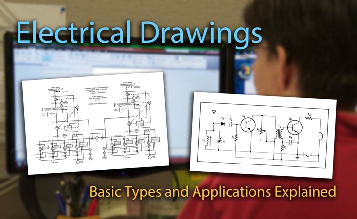
Electrical Drawings And Schematics Overview from testguy.net Network diagrams form the blueprints for security programs in the 21st century. The electron shells are shown, moving outward from the nucleus. The element atomic number and name are listed in the upper left. Building the systems diagrams requires four steps; Properties elements cannot be broken down chemically or physically. In electrical and electronics engineering, we use different types of drawings or diagrams to represent a certain electrical system or circuit.these electrical circuits are represented by lines to represent wires and symbols or icons to represent electrical and electronic components.it helps in better understanding the connection between. There are many types of conductors used in. Class diagram consists of classes, interfaces, associations, and collaboration.
Identify the types of elements in the schematic diagram above and the number of each type.
What physical characteristic of the atmosphere changes as altitude increases? Uml diagrams generally permit the annotation of comments in all uml diagram types. Emphasize connections between elements of a circuit or system 2. To help them design the actual circuits. Table 1 comparison between wiring and schematic diagrams wiring diagrams schematic diagrams 1. Different types of electrical diagrams and drawing. Properties elements cannot be broken down chemically or physically. The arrow symbol represents relationships. Schematic diagram, the symbolic elements are arranged to be easily interpreted by the viewer. Class diagram represents the object orientation of a system. Answer to identify the types of elements in the schematic diagram illustrated in figure 1.5 and the number of each type.figure 1.5. Identifying elements and compounds from particle diagrams. As the name suggests, a package diagram shows the dependencies between different packages in a system.
For example, c1 is the first capacitor, l1 is the first inductor, q1 is the first transistor, and r1 is the first resistor. The flow of creating systems thinking diagram. A schematic diagram uses symbols to represent the various parts of a circuit. The basic graphic notation elements of dsds are boxes which represent entities. A schematic, or schematic diagram, represents the elements of a system with abstract and graphic symbols instead of realistic pictures.a schematic diagram focuses more on comprehending and spreading information rather than doing physical operations.
2 from Symbols are used to indicate conductors,. Data structure diagram (dsd) is a diagram of the conceptual data model which documents the entities and their relationships, as well as the constraints that connect to them. Class diagram consists of classes, interfaces, associations, and collaboration. As the name suggests, a package diagram shows the dependencies between different packages in a system. Schematic diagram is essentially data that shows different elements of specific systems. To help them design the actual circuits. Different types of electrical diagrams and drawing. Identifying elements and compounds from particle diagrams.
The basic graphic notation elements of dsds are boxes which represent entities.
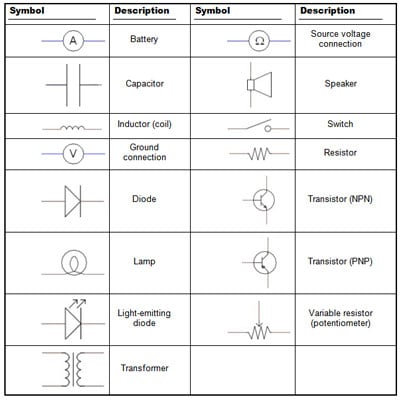
As the name suggests, planimetric diagrams show plans, i.e. Data structure diagrams are most useful for documenting complex data entities. Uml diagrams generally permit the annotation of comments in all uml diagram types. Identify the types of elements in the schematic diagram illustrated in figure 1.5 and the number of each type. To be fair, documenting one's network is tedious. Schematic diagram, the symbolic elements are arranged to be easily interpreted by the viewer. Identify the types of elements in the schematic diagram above and the number of each type. Just as the road map uses symbols to represent the highways, cities, interchanges, and other elements displayed, the schematic diagram uses symbols to represent the components used to make up a circuit. Some diagrams can also contain words, such as when a process contains multiple elements that have not been standardized. The block normally contains the name of the element (figure 1b) or the. A circuit diagram is a simplified representation of the components of an electrical circuit using either the images of the distinct parts or standard symbols. The two most commonly used are the wiring diagram and the schematic diagram. Symbols are used to indicate conductors,.
Different types of electrical diagrams and drawing. An extensive collection of electrical diagram templates can be found in the electrical engineering category. Just as the road map uses symbols to represent the highways, cities, interchanges, and other elements displayed, the schematic diagram uses symbols to represent the components used to make up a circuit. There are many types of conductors used in. What physical characteristic of the atmosphere changes as altitude increases?
Electronics Schematics Commonly Used Symbols And Labels Dummies from www.dummies.com Table 1 comparison between wiring and schematic diagrams wiring diagrams schematic diagrams 1. It consists of a single block with one input and one output (figure 1a). An extensive collection of electrical diagram templates can be found in the electrical engineering category. Three types of schematics are the single line diagram, ac schematic diagram and dc schematic diagram. What physical characteristic of the atmosphere changes as altitude increases? Active class is used in a class diagram to represent the concurrency of the system. Profile diagram is a new diagram type introduced in uml 2. In order to build the systems thinking diagram, we need to clearly identify the elements of the system and how it interacts with each other.
Answer to identify the types of elements in the schematic diagram illustrated in figure 1.5 and the number of each type.figure 1.5.
Made of one type of atom with their own unique properties. From this, the actual workings of a piece of electronic equipment can be determined. It consists of a single block with one input and one output (figure 1a). Figure 3 is an example of an electronic schematic diagram. Report will identify methodology behind these practices, present issues raised by the. The arrow symbol represents relationships. To help them design the actual circuits. Symbols are used to indicate conductors,. Class diagram represents the object orientation of a system. Building the systems diagrams requires four steps; Some diagrams can also contain words, such as when a process contains multiple elements that have not been standardized. A schematic diagram uses symbols to represent the various parts of a circuit. Launch edrawmax on your computer.